Centrifugal Impeller Design Types and Uses
Impeller Types
Impeller types in Centrifugal Pumps vary in design depending on the fluid being handled, whether design is low or high pressure, and if the unit designed is self-priming or to handle entrained gas.
Care must be taken during selection to ensure a correct balance is achieved between desired outcome for the process and maintenance periods, whilst ensuring maximum process efficiency is obtained.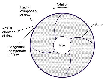
Applications
There are 10 types of impeller each having different advantages and disadvantages depending on the application.
Typically, the closer that radial vanes are together, the tighter the tolerances and more enclosed impeller design, the higher the efficiency and lower the solid handling capacity due to limitations in free passage.
Below is a list of the 10 different types, their advantages and types of fluids they may be used with:
Impeller types and flow pattern
Closed or Enclosed (Centrifugal, Multistage and First Stage of Side Channel Pumps)
Designed for clean fluids with small particles, it is the design with the highest efficiency due to its tight clearances against the internal casing but also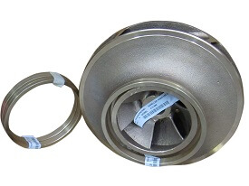 between impeller blades.
The solid handling capability is defined by the space between the front and rear channels in the impeller which for small units could be measured in microns.
Fluid is drawn into the impeller eye (centre) before centrifugal forces direct fluid through blades, then directed towards the side of the pump casing, and expelled through the outlet.
Double Suction (Split Casing and Double Suction Designs)
Used predominately in Split casing pumps, this design enables the pump to draw liquid through both sides of the impeller blade simultaneously. 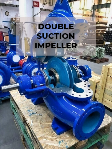
Typically used for clean liquids, without solids at high flows and relatively low heads with a double volute casing feeding both sides simultaneously. This unit delivers the highest flow possible within a single casing.
Flexible (Flexible Impeller Designs)
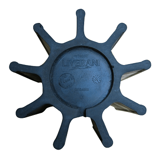 This design consists of curved rubber vanes which remain in contact with the pump casing enabling the unit to be self priming. Designed to handle clean, viscous and solid laden liquids, solid particles fit between the blades meaning the unit can handle suspended solids such as fruit chunks up to 25mm in diameter.
Low shear by design, rotational speed is less than 1400rpm due to the impeller touching the casing.
Open 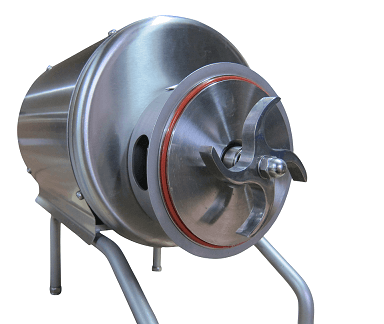
In this design only the vanes are visible enabling the unit to handle large solids, and remain easy to clean. It has a lower efficiency that other types due to its large free passage area. This design struggles to generate high pressures due to the lack of side walls, but can accommodate large solids.
Semi-Open (Centrifugal and Trash Pumps)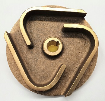
Within this shape, wide channels enable the handling of large solid particles without clogging. Designed for large capacities and low pressure for the handling of sewage or in aggressive process applications found within industry.
Sinosuidal
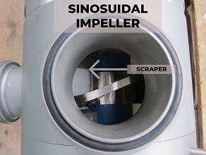 Its appearance is similar to that of a sinosuidal sound wave which is unlike any other design. It is designed to scoop pieces transferring them gently towards the outlet, with a scraper at the outlet ensuring fluid is not recirculated within the pump head. The scraper moves in and out inline with the wave shape of the impeller.
The impeller does not have a tip unlike other low shear designs of pumps, meaning it can transfer soft or damage prone products without breakage, such as fruit pieces as they do not pass through the impeller.
Vortex (Submersible, Process Pumps)
Traditionally liquid flows through the impeller before being expelled radially towards the casing outlet however this version creates a vortex within the casing enabling the passage of fibrous materials or solid particles which often do not come into contact with it. Only a small percentage of particles make contact with the rotating part, with this design also referred to as non clogging. 
Predominately used for low head applications, it can be recessed within the pump casing to enable larger suspended solid passage without contact to pumped solids.
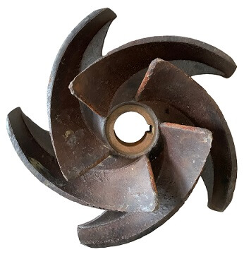
Mixed Flow (Semi Axial) (Vertical Turbine & Immersion Designs)
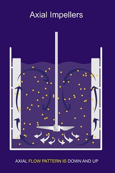
This design transports flow diagonally. Due to the strong vertical currents it makes, if immersed within a tank it prevents settling at the bottom.
Cutter (Submersible and Centrifugal)
Cutter impellers can be of various designs depending on whether the unit is of cutter or macerator design.
Macerator designs can have a tungsten carbide impeller rotating in conjunction with a diffuser plate and grinder macerating solids. Models may also can have an agitator installed on an extended motor shaft located below the impeller, acting as a stirrer ensuring matter at the pump suction is broken up and transferred through the pump.
An example of such a model is the Tsurumi C Series.
Cutter designs contain a multi vane channel impeller with cutting mechanism working against a stationary cutting ring, and rotating knife. 
This enables the unit to deliver higher pressures than a solid handling pump utilising smaller pipework making it ideal in situations where high pressures are needed and pipework size needs to be kept to as small as possible such as in long discharge lines or within a sewage pumping application when an additional bathroom may be added in a property within a basement.
<img source :https://www.tsurumi-global.com/products/submersible-pump-C/ >
Side Channel (Side Channel Pumps in Combination with Closed impeller)
This multiple radial designed shape enables the unit to handle entrained gas, fitting tightly between a suction and discharge casing to maintain efficiency.
Unable to handle solids it separates gas or air allowing both to be pumped without vapour locking, thus making it self-priming.
10 Common Problems
1. Clogging
Where pumped fluid congregates within the casing, reducing clearances and pump efficiency leading to a reduction in flow rate and pressure.
2. Chemical Attack
Where liquids or chemicals not compatible with the material of the pump lead to corrosion and failure of parts.
3. Cavitation
When there is a lack of suction pressure, it can lead to bubbles forming within the suction, which collapse then implode on the impeller surface, eroding large areas quickly leading to failure.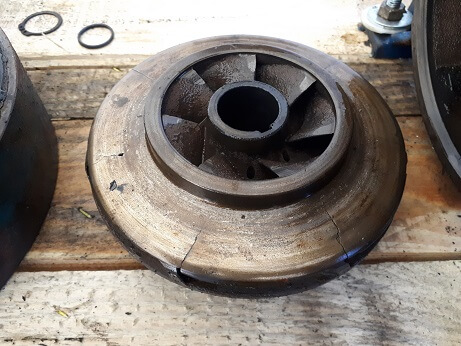
4. Imbalance
At manufacturing stage all impellers are balanced. If these are not balanced it leads to unequal radial forces and associated accelerated component wear due to heavy vibration. This directly affects the lifespan of the mechanical seal, and bearings leading to premature pump failure.
5. Water Hammer
Water hammer is the sudden stopping of a fluid causing momentum present in the liquid to reverse flow, travel back and forth rapidly creating vibration. This can cause impellers and casings to crack due to the forces involved.
6. Loose
Impellers have the possibility of becoming loose when vibrations occur within the unit. This consequently leads to the part coming into contact with wear rings, or pump casing at speed causing destruction of the unit.
7. Resonance
With the fitting of Variable Speed Drives assumptions can be made that a pump can be operated at any rpm. Some RPM’s can create resonance within pump parts leading to vibration.
8. Fouling
Fouling can reduce the free flowing path of liquids reducing efficiency. If pumps have been stood for some time growths can occur, not only within the pump but within suction pipework in marine environments known as biofowling.
This can lead to cavitation within units and If designs are chosen with closed impellers which then encounter solid particles, these can clog internal passage.
Some liquids which contain dissolved solids which separate once fluid stops or when dry such as those used in scrubber applications can lead to calcification / limescale build up also reducing efficiency.
9. Turbulent Flow
When flow is turbulent and not laminar, it can create separation of the pumped fluid occurs but it also creates the ideal conditions for cavitation to occur.
10. Overpressure
High inlet pressures can force impellers against wear rings, or stage casings drastically reducing service life.
Trimming
Impellers undergo trimming to enable pumps to meet specific duties. Typically units are manufactured with impellers at full size, and when used with an inverter the rotational speed can be reduced to reduce the flow and pressure to meet the required duty point. By keeping the impeller at full diameter, clearances between the rotating part and casing are kept small maintaining efficiency.
Trimming impellers is another way a pump can be made to meet a duty point, however the more material that is removed, greater internal tolerances are created within the casing reducing efficiency.
The speed of rotation and diameter of the rotating part are used as a predictor of performance and are known as the affinity laws.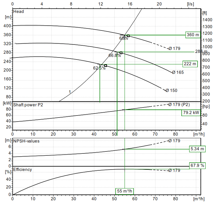
Centrifugal Affinity Law
Pump affinity laws are a set of formula which can be used to determine a units performance when a change is made such as speed, or impeller diameter to the produced flow and pressure with a high degree of accuracy.
There are 3 affinity laws:
1) Flow is proportional to the shaft speed or impeller diameter
As the shaft speed or the impeller diameter is altered, the flow will change by the same amount. If the speed of a pump is reduced by 20% the flow at the same head will also decrease by 20%.
2) The pressure produced is proportional to the square of shaft speed or impeller diameter
When the impeller diameter is altered or shaft speed is changed pressure changes proportional to the square of the change in shaft speed or impeller diameter. If a shafts speed increases by 10% then pressure at the same flow will increase by 21%
3) Power is proportional to the cube of shaft speed or impeller diameter
If the shaft speed increases by 10%, then due to power being proportional to the cube of shaft speed the pressure will increase by 33.3%.
Wear rings sit either side of the impeller to act as sacrificial parts to prevent casing wear and maintain efficiency within the casing. A doubling of wear ring clearances can lead to NPSH increasing by as much as 50%.


