What Are Gear Pumps?
Gear Pump Guide
What is a gear pump?
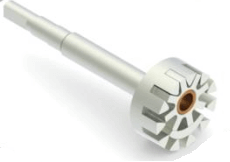
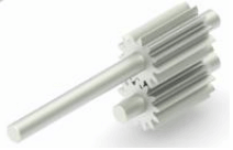
A gear pump is a rotary positive displacement pump that can be of two designs – Internal Eccentric or External (also known as helical gear).
The design chosen for a process is dependent on the viscosity of the fluid and pressure required as the internal design is altered according to fluid type with differing styles of teeth fitted to suit conditions which limits rotational speed.
They are very versatile being self-priming up to 6.5M, positive displacement generating non-pulsating flow and handling viscosities between 1 CST and 1,000,000 CST.
How does a Gear pump Work?
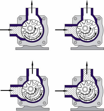
Gear pumps operate via two idler gears, where fluid travels between cavities within the teeth and cavity. The fluid is trapped by the teeth as they rotate. As a fluid chooses the path of least resistance fluid flows towards the discharge via the meshed parts. There are two variants in design being either External or Internal.
What is an External Gear Pump? (Helical / Modular)
A helical / External unit is chosen when a viscous fluid which will be transferred at low rpm, and where a smooth discharge of fluid is required.
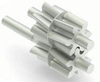
This type of pump produces less noise than an internal eccentric design typically because of the lower speed it operates at but also due to the design of the teeth. As the helical parts are offset at an angle within the pump head a second set of helical gears are situated behind the main teeth to ensure the unit remains balanced.
Gears are mounted above each other within the head with one being driven by the motor. They are timed to mesh with fluid flowing into the open cavities, rotated in between the teeth and casing and transferred to the outlet.
What is an Internal (eccentric) Gear Pump?
Operation within an internal design is similar to an External type in that the spaces between the teeth in the pump are filled with liquid. The liquid must be clean due to the gaps between the teeth being small.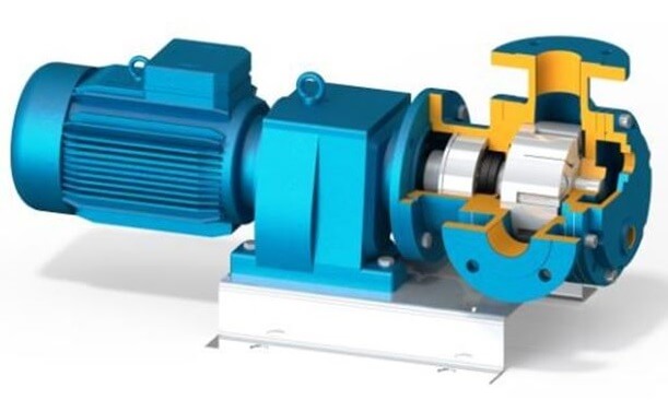
Liquid enters the meshed cogs, with part of idler sealing the inlet and driving the fluid towards the outlet.
The Seal types used within the various designs of pumps are a single mechanical seal, double mechanical seal, gland packing/stuffing or magnetic coupling where no seal is present.
Heating jackets operated via electricity or separate heat transfer fluid can be fitted to both styles of the pump to ensure liquids do not solidify within the pump head.
Internal & External Gear Pump Comparison Table | |
Internal Gear | External Gear |
2 Working Parts – Rotor & shaft, and idler gear | 2 Interlocking gears, mounted on separate shafts |
2 bushings for shaft support. One bearing within the liquid | Typically 4 bushings which are immersed within the liquid |
Medium pressure design up to 15 bar | High Pressure design up to 30bar |
Up to 200M³H | High Flow Design (up to 300M³H) |
Adjustable end clearance. | Fixed End clearances meaning slip is inevitable |
Handle small solids | Unable to handle solids |
Cog Design | Cog Design |
Working Principle | Working Principle |
Designs Available:
There are various customisations available for units which include:
Flanges: Inlet and outlet can be manufactured as inline or at 90° angles to match pipework.
Single Jacket: A heating jacket is fitted on one part of the casing to prevent solidification of viscous fluids being pumped or to maintain a fluids viscosity. Example fluids are Chocolate, Bitumen, molasses and Heavy Fuel Oil.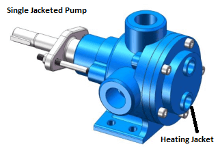
The same ports can be used to function as a cooling jacket ensuring the liquid being pumped maintains its temperature or kept cool. On some designs this feature can mean a relief valve can not be fitted. Fluids which can be used for jackets are oil, steam, and water. Electricity can also be used.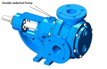 Double Jacketed: Heating or cooling jacket is fitted on both sides of the pump casing. On some designs this feature can mean a relief valve can not be fitted.
Relief Valve: A relief valve to prevent the pump from over pressurising, relieving pressure to the inlet.
Seal Types: The Seal types used within the various different designs of pumps are a single mechanical seal, double mechanical seal, gland packing/stuffing or magnetic coupling where no seal is present.
Blind Cover: A blank cover on the face of the pump.
Why choose gear Pumps?
They offer many advantages, mainly:
Low Shear – Their design and operating speed is low meaning movement is low shear.
Self Priming – They are self priming up to 6.5M.
Reversible – Due to their design they can operate in both directions, ensuring hoses can be emptied and allowing full recovery of any products. However, the relief valve will only operate in one direction.
Efficient – Models are up to 85% efficient.
Predictable – Flow is proportionate to speed ensuring repeatable and predictable flow rate.
Non Pulsating – The smooth rotary motion at low rpm means pulsations are not experienced as is more common with other positive displacement designs.
Materials – Designs are in complete metal meaning units can be Atex rated (explosion proof), handle solvents as internals parts are not rubber as in other positive displacement pumps. They can also accommodate high temperatures of up to 350°C.
Limited dry running - Units can run dry for a limited time providing the gears have been immersed in a lubricating liquid.
Low NPSH –NPSH requirements are very low due to their slow operation. Internal gear pumps NPSH ranges from 0.5M to 4M based on water, with external designs generally being up to 3M.
To correctly apply the values to another fluid the NPSH should be divided by the specific gravity. If pumps are operated at an incorrect speed or NPSH available is too low, it is possible for units to cavitate. NPSH is usually not considered an issue with such designs of pump.
Applications
Applications typically tend to be for the circulation, transfer or metering of precise amounts of liquids.
They can be used across various industries such as:
Fuel Industry: Lube oils, furnace, diesel, grease and waste oil.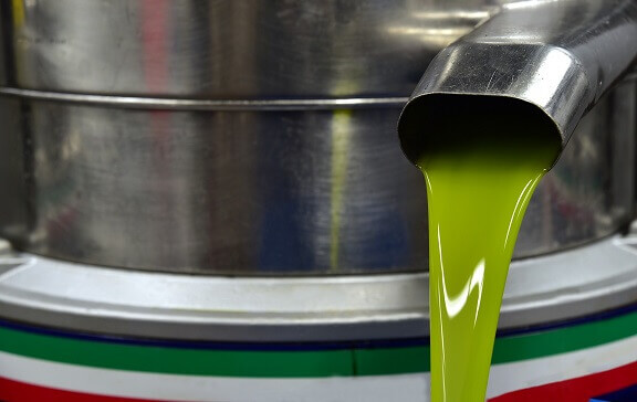 Food Industry: Transfer of Syrups, Chocolate, Honey, Creams, molasses
Construction: Polyurethane, bitumen and fillers.
Paint: Paint, inks, latex.
Chemical: Handling of Resins, soaps, pigment, polymers, chemicals and polyurethane. They are also used in extrusion.
If gears are designed with plastic or PTFE parts they can be used for water or non-lubricating liquids.
Gear Pump vs centrifugal |
After 200cst the efficiency of centrifugal pumps drops significantly making them unsuited for viscous liquids |
Provide constant pressure despite fluctuations in viscosity |
Gear pump vs diaphragm pump |
Higher pressure handling |
No valves to clog or be over pressurised to open |
Reversible |
Gear pump vs peristaltic pump |
No Pulsations |
Construction is of metallic parts so less prone to wear |
Handle solvents,& chemicals |
Gear pump vs vane pump |
Abrasive Solids are a challenge |
Pumps can be much larger for viscous fluids compared to other types. |
Gear pump vs lobe pump |
Utilised less seals 1 against 2 |
Timing cogs are not required |
Up to half the cost of lobe |
Easier to maintain and rebuild |
Gear vs Progressing Cavity |
Compact Design |
More material choices |
Lower cost |
More tolerant of dry running |
Seal less |
Handle solvents |
Repair costs lower |
What are the limitations of such designs?
Wear - Susceptible to wear with abrasive solids, sediment, solids. As the ends of cogs are a fixed length, once worn slip will increase with a corresponding decrease in output.
Parts in Pumped liquid – Bearings are in the pumped liquid within external types meaning such designs are not suited for abrasive liquids. Bearings and bushings must be checked for wear and vibration.
Level of hygiene – Due to the cog design, and bearings or bushing immersed in the liquid, high levels of hygiene are not always possible. Other designs such as lobe or flexible impellercan provide better levels of hygiene.
Solid Handling – Units can be oversized to increase tolerances between internal components allowing solids but reducing efficiency.
There are a range of symbols used to represent Gear Pumps in P&ID Drawings which can be viewed here.
Experiencing issues? View our troubleshooting guide
Interested in the types of units we can offer? View our range
FAQS
There is a lot of crossover between models, with a final design chosen by efficiency and lowest lifetime cost.
Firstly, the gears require lubrication from the pumped fluid, for example fuel and oil. Dry running without these will cause fast and irreversible damage.
The mechanical seal requires lubrication and cooling while the pump is operating. Without the presence of fluid, the mechanical seal will overheat and crack, and this may cause the pump to leak and fluid to enter the motor.
There is also the possibility that the motor will burn out. Our advice is to ensure that the pump always has access to fluid while running, the vessel or sump on the inlet side of the pump must never run out of fluid while the pump is active.
Level sensors or a float switch can be installed in the fluid chamber ensuring that the pump is turned off in the event there is no fluid. Another way of protecting the pump is to fit a dry running device, this will turn the pump off if it detects that no fluid is entering the pump. If you think that dry running is inevitable, then please speak to us and we will try to select a more suitable pump for your application.
Typically set to around 10% higher than the working pressure, it will open and recirculate the fluid inside the pump head when a set pressure is achieved.


