What Are Positive Displacement Pumps?
Pumps are categorised into one of three main families; rotary positive displacement, reciprocating positive displacement, and centrifugal. Which pump technology is chosen for an application depends on a variety of reasons: the viscosity of the fluid, type of liquid being pumped, its abrasiveness, temperature and duty point required.
This article will provide an overview on what are rotary pumps and reciprocating positive displacement pumps, also known as PD. We'll also dive into why they are important, when a certain type or design is most appropriate for an application, and finally, 8 Reasons to select a positive displacement pump for your application.
What Are Positive Displacement Pumps?
Positive displacement (PD) pumps are designed to ensure that any pumping action is forward (positive). Its internal design ensures and prevents fluid from recirculating back towards the pump inlet, or within its casing.
PD pumps can be of rotary or reciprocating positive displacement design. With differing internal parts, and designs to accommodate a variety of fluid characteristics.
Certain principles are common across rotary and reciprocating pumps due to their design.
These designs have the following characteristics:
A fixed volume of fluid transferred per revolution
Pressure remains constant
Flow is proportional to speed
How Do Positive Displacement Pumps Work?
There are more than 10 different types of positive displacement pumps. To explain their operation in simplistic form, PD pumps function by fluid being drawn into a chamber, or cavity by creating a vacuum.
Once the chamber is filled, the pump cycles causing the fluid present within the pump head to increase in pressure. This then causes it to be discharged via the discharge port into the pipework.
Types of Positive Displacement Pumps?
There are two families of PD pumps which are rotary and reciprocating positive displacement, they can be electrically, hydraulically or engine driven, and manufactured in almost any material to enable use across a variety of industries and applications.
Rotary Positive Displacement Pumps
Rotary positive displacement pump types of function by a rotary action producing flow and pressure. Examples of these pump designs include. Vane, internal & external gear, lobe, peristaltic, screw and progressing cavity.
Reciprocating Positive Displacement Pumps
As opposed to reciprocating positive displacement pumps. These pumps operate by converting an attached motors rotary forces into reciprocating motion. Examples of these designs include piston, plunger, and air operated diaphragm pumps (AODD).
Advantages of Positive Displacement Pumps
Such pump designs have various advantages for applications. Here are 6 advantages of positive displacement pumps:
1. Accurate Predictable Flow
As chambers within such pump designs contain a fixed volume - flow is proportional to speed. Calculations can be made with a high degree of accuracy of the flow produced per revolution. This enables estimates for the expected output or flow of the pump over a period of time.
2. Wide Viscosity Handling
These designs are unaffected by viscosity, meaning should the viscosity increase with temperature, equipment used with a variety of differing fluids, or the liquid being pumped, behave as a non-Newtonian fluid.
This is when viscosity increases with shear, known as shear thickening with the flow or pressure capabilities of the unit not being affected.
In-fact PD pumps prefer thicker fluids, with a fluids higher viscosity usually helping to generate higher pressures and flows.
3. Consistent Pressure
These types of units provide a constant pressure at pressures up to several bar higher than the required duty point. Compared to centrifugal pumps where a particular pressure and flow is only produced at a single duty point.
This can be useful in applications where discharge pressures vary. Such as in tanker loading, spray applications or in dosing and metering applications.
4. Lower Wear and Tear
PD pumps operate at reduced speeds when compared to centrifugal pumps. This lower speed enables the handling of abrasive or solid laden liquids which would wear parts in a centrifugal pump.
5. Preservation of Liquid Characteristics
Reducing pump speed enables pumps to be oversized, meaning the flow or pressure requirements of an application are met by a unit operating slowly.
This reduces wear and ensures that the liquid remains unaffected by the pumping motion, preserving its characteristics. This is especially important with liquids which are shear thickening, such as milks, creams, polymers, and gels.
6. Non-Slip Designs
All pumps have a minimum and maximum viscosity level, which is the viscosity limit they are engineered and designed to handle. If fluids are heated causing their viscosity to reduce to a level less than that designed limit, then pump will be unable to handle it and slip will occur.
Pump slip is where fluid recirculates within the pump head, causing a reduction in flow and pressure generated by the pump. This means fluid can continue to recirculate within the pump head and if left undetected can overheat causing the mechanical seal to fail.
Non-slip designs of positive displacement pumps are available. These designs ensure whatever a fluids viscosity, pump slip will not occur – like in this case study.
Disadvantages of Positive Displacement Pumps
There are certain disadvantages to positive displacement pumps. Here are details of the most common 7:
1. Flow Restricted
Flow is restricted due to its internal design on some pumps, meaning flow will be less than a centrifugal pump for low viscosity fluids. Some designs of positive displacement pumps are completely ruled out for certain applications. This is due to the flow not meeting the needed requirements for an intended application.
2. Difficult to Maintain
Due to their internal design they can be difficult to maintain. This can be because of the number of parts and size of parts, how they fit together and the liquids they are used with usually being thick, corrosive, dangerous, and encrusting/coating parts within the unit, meaning maintenance is more time consuming.
It's common for two or more personnel being required for positive displacement pump maintenance, meaning more labour is required to service such designs of pump.
3. Service Intervals
Due to the tight clearances, demands of applications, contact of internal parts and abrasive liquids used, service intervals tend to be more frequent than that of centrifugal designs.
4. Pulsating Flow
Flow can pulsate meaning pulsation dampeners are required to minimise pulsations. This can affect the reliability of flowmeters, the coating of liquids on to surfaces in a smooth consistent fashion and reliable metering of fluids into process or containers in container filling applications.
5. Cost Effectiveness with Low Viscosity Fluids
Such units are not usually cost effective for low viscosity fluids, or fluids which need transferring at low to medium flows where a centrifugal Pump could be used.
6. Not the cheapest solution
When positive displacement pumps are used, they are usually specified to ensure the consistent metering, transfer, and flow of liquids.
Built differently to centrifugal designs and designed for fluids much thicker than water, they are never the lowest cost option, but they are often the lowest lifetime cost solution. This is the case in applications, where fluids are abrasive, contain solids or vary in viscosity.
7. Required accessories for System or Operator Protection
PD pumps are great at building pressure within discharge pipework, but they can be too effective which can cause other issues.
If left unrestrained, Positive displacement pumps will continue to build pressure in outlet pipework, until something gives relieving the pressure. This can be a valve, the pump itself or pipework, which is why quite often units are supplied complete with integrated relief valve.
Some designs of pumps such as AOD will stall or pause when outlet pressure reaches its maximum output. Other designs such as piston, need relief valves to reduce pressure or a pressure regulating valve to control the pressure to a set value.
-24042914471642722.png) Positive Displacement Pump Curve
Positive Displacement Pump Curve
A positive displacement pump curve differs to that of a centrifugal pump curve as the performance does not peak and then reduce as on a centrifugal pump performance curve - which shape resembles that of a bell.
In-fact positive displacement pump curves usually consist of several straight lines as in the image below, with a line per set pressure detailing the performance at that pressure against the speed the unit is operated at.
The curve differs to a centrifugal pump as it details the flow by pump speed. As opposed to a centrifugal pump where the speed is fixed, with the maximum flow and pressure available from the unit on the right of the performance chart.
Positive Displacement Pumps Applications
Such designs are used in a variety of applications due to their versatility and variations in design.
Typical applications they can be found in include:
Tanker Unloading and Loading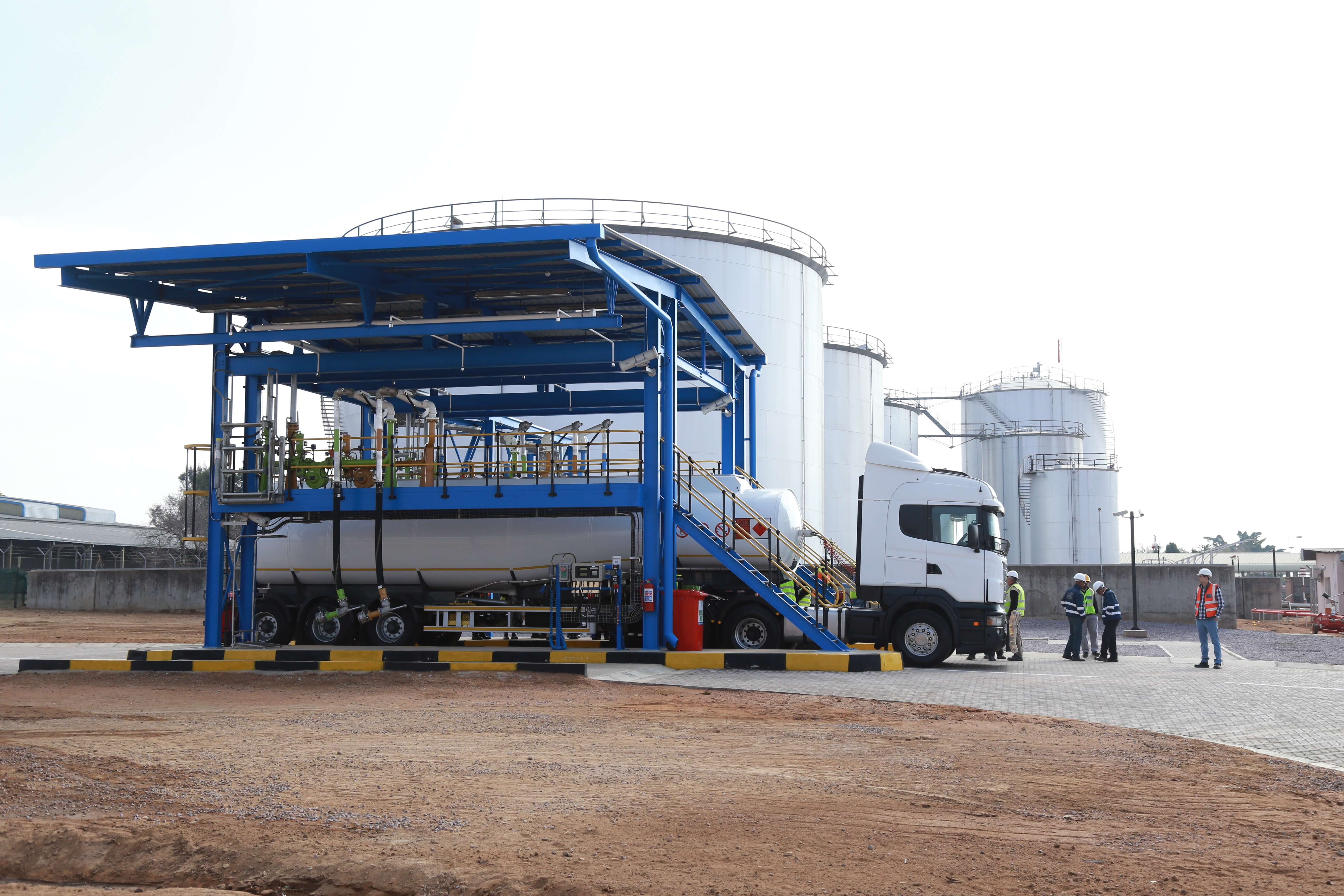
Usually fuels, but also chemicals, food ingredients and oils, to other fluids ranging in viscosity from those thicker than water to sludges.
Using positive displacement pumps ensures tankers can be stripped (completely emptied), with dry run designs ensuring pump damage does not occur. They are very effective at priming and ensure siphoning doesn’t occur where once the pump is stopped as in centrifugal designs.
Metering, Dosing and Sampling
Precise repeated delivery of fluids into a process means any pump selected must provide a set volume per revolution. This rules out centrifugal designs where it is possible for fluid to vary in flow or recirculate within a pump head.
Fluids used in these processes can vary by application but can include chemicals such as flocculants, coagulants in wastewater treatment, chemicals, flavourings, fuel, dyes, or paint. PD Pumps are known for their accuracy enabling dosing accuracies > 99% to be achieved.
Transfer applications
High Viscosity Fluid Transfer
They handle high viscosity liquids without loss of flow or pressure which is needed in industrial factories, such as clean oils, waste oils, or greases. Also, in food factories where pastes such as tomato, jams, sauces, chocolate, and other ingredients may be transferred. And in pharmaceutical plants where polymers, creams and pastes be dosed or transferred.
Solid Transfer
To handle solids present within fluids, either suspended within the liquid or, in concentrated form and need reducing in size, or breaking apart or separating to be pumped.
They are also found in applications where dry solids are pumped in anaerobic digestion plants or spent grain in distilleries.
Lubrication
For the lubrication of equipment where coolants or oils may change in viscosity as they are heated or become contaminated with solid particles and sludge.
Container Emptying
Used for the emptying of viscous liquids from barrels, which can include cosmetic products, tomato paste, grease, resin, wax, glues, polymers, or slurries.
Viscous & Sensitive Liquid Transfer
PD pumps preserve the characteristics of fluids, making them ideal for the transfer of viscous and sensitive liquids.
This could be milks and creams that can become thicker if pumped at too high speed, or for preserving cell culture by using designs of pumps with a high solid passage or gentle pumping motion. Such designs ensure that the liquid transferred is consistent with each batch.
Varying viscosity or high viscosity
A centrifugal pump is sensitive to fluid viscosity. Risk comes from the fluid being more viscous than expected, changes with temperature or a variety of fluids used with the same pump. This could affect the output and duty performed by the pump being less than expected.
This is because as fluids become more viscous, they become harder to pump. The energy required for them to flow through pipework increases. Furthermore, as viscosity increases the efficiency of centrifugal pumps decreases leading to recirculation within the pump head.
Positive displacement designs prefer viscous liquids. Meaning should the viscosity or temperature change you can guarantee consistent output.
Variable pressure losses
In applications where pressure loses can vary. This could be due to viscosity, temperature, changing flow distances, or the number of opened outlets. It could also be opened nozzles such as in spraying applications.
Flow combinations – High Pressure Low Flow, or Low to Medium Flows.
For a variety of flow combinations. These could be high pressure with low flow requirements, or low flow and low pressure demands. PD pumps range in pressure generation capabilities from a few bar to thousands often in more compact designs.
Our pump wheel can enable users to establish which pump type is best suited to handle your process.
8 Reasons to use a Positive Displacement Pump?
Below are 8 reasons why a PD pump may be most appropriate for your application:
Viscosity is higher than 300cst
A fixed volume of flow is required across a range of pressures
Viscosity varies
Back pressure may change
Metering
A Low Flow rate is required
High pressure discharge
Shear Sensitive liquids
Parts of a positive displacement pump
There are many different internal parts to positive displacement pumps. There main parts are listed below grouped by pump designs, with common parts listed at the end.
Air Driven Diaphragm Pumps (AOD)
Diaphragms (Internal & External)
Diaphragms are housed within the chambers of air operated diaphragm pumps which have two sides – an air and fluid side.
The air side is the side of the diaphragm which expands and contracts being closest to the central air valve. The fluid side meets the fluid, filling and contracting with fluid as the pump cycles.
The two sides are often different materials. Typically manufactured from one piece, unless of PTFE (synthetic fluoropolymer of tetrafluoroethylene). Which isn’t flexible enough to provide the performance needed, meaning it is double backed.
Balls
These are manufactured in a variety of plastics and metals depending on the fluid being pumped. They act as valves above and below each side of the diaphragms, below the top manifold and above the bottom manifold. They are responsible for maintaining pump efficiency and ensuring the pump can operate.
Seats
Diaphragm pump balls push against seats to form a seal isolating each chamber within an AOD pump.
Ball Cage
The balls located above and below the pump diaphragms are housed in cages. This to prevent the balls from damaging the tops of the manifolds and to stop them sticking to the top of the pump.
Silencer or Air Muffler
Quietens the sound of air discharge from the pump.
Centre Nut
This holds parts of the pump together e.g., manifolds, diaphragms etc.
Washer
Used in conjunction with the nut to prevent the nut from moving or corroding.
Air Valve
The air valve is located in the central manifold of the pump. Its purpose is to convert air flow and pressure into reciprocating movement. This drives a piston to compress one diaphragm then another.
Manifold
Manifolds are located at the top and bottom of AOD Pumps. The suction manifold is designed to keep the pump diaphragms flooded with fluid. They act as a single delivery pipe on the pump discharge
Electric Diaphragm Dosing Pump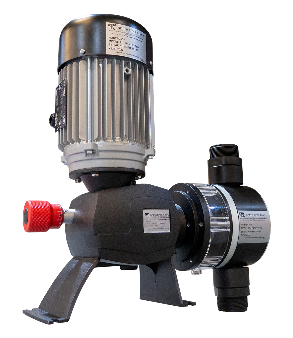
Piston Cylinder Ring
Maintains Seal around the outside of the cylinder.
Regulating Rod
This regulates how far the piston compresses the diaphragm via a dial at the rear of the pump. This is usually a setting between 0 – 100% of displacement.
Piston
This is driven via a gearbox and moves in a reciprocating motion compressing the diaphragm. When the diaphragm is compressed, fluid exits the pump head via the discharge valve. When the piston draws back the diaphragm expands drawing fluid into the pump head via the suction valve.
Suction/Discharge Valve
Responsible for sealing the pump head, ensuring that fluid drawn into the pump head and does not leak out. Also, that displacement is always via the discharge valves.
Diaphragm
These fill with fluid and are compressed by the piston. This happens at varying frequency and depth to produce the required flow.
Flexible Impeller
This is a rubber impeller which sits inside the pump casing. When inside the casing, several of the vanes are bent over forming a tight seal within the casing.
They are made from a variety of rubbers such as EPDM, NBR, Silicone, Viton, and Neoprene.
Gear
Heating Jacket
These maintain the liquid temperature within the pump head preventing solidification. This ensures the liquids viscosity remains within the handling capabilities of the pump.
Rotary Gear
Found within internal gear pumps, this is fixed in place with a smaller idler gear driven by the pump shaft.
Idler Gear
The idler gear rotates within the rotary gear, driven by the pump shaft drawing fluid into the pump head. This builds pressure before its discharged via the outlet of the pump.
Helical Gears
These are two interlocking gears mounted on separate shafts working in unison. They draw fluid around the outside of the pump casing. This fills the pump head before liquid builds in pressure and is discharged via the outlet.
Peristaltic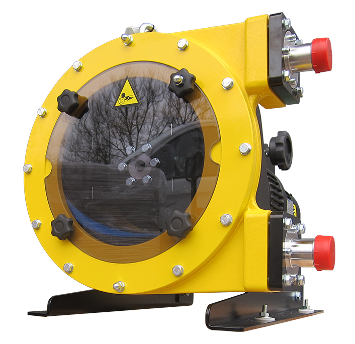
Hose
The only wearing part of a peristaltic pump. The hose is compressed by rollers or shoes causing the transfer of liquids.
Rotor
The rotor is driven by the output shaft of the gearbox. This then rotates the shoes or rollers which compress the hose.
Shims
Shims are placed under shoes and rollers which alters the amount of hose compression and consequently the pressure generated by the pump.
Shoes
These compress the hose enabling pressures up to 15 bar to be generated by the pump.
Rollers
These elements compress the hose, enabling pressures up to 8 bar to be generated. Their use extends hose life as well as using 30% less energy, enabling the pump to start from 1Hz. This allows for a greater flow range capability, and lower amounts of hosing lubricant.
Piston / Plunger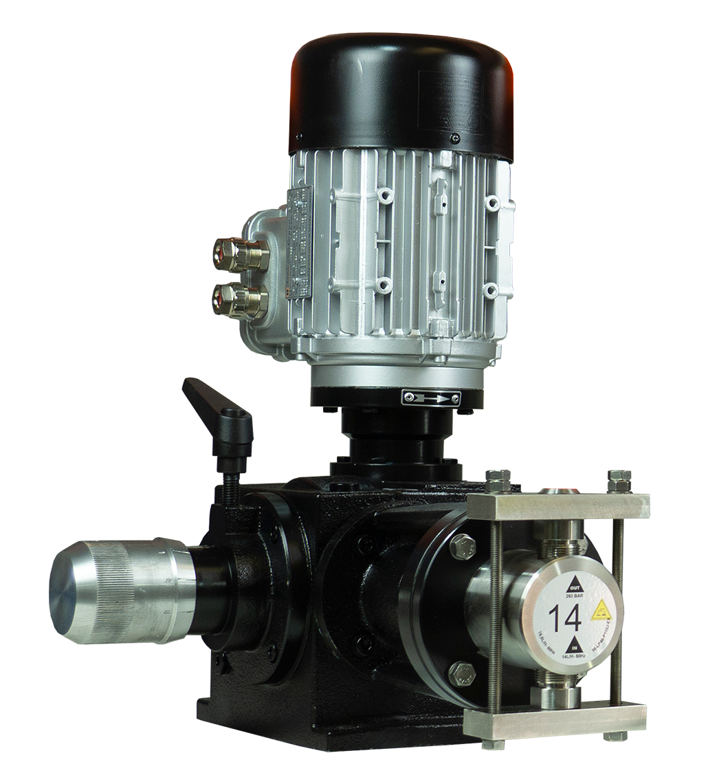
Crankshaft
This converts rotary movement into reciprocating movement, allowing the driving of plungers or pistons at separate time intervals.
Discharge Manifold
Pressure and flow generated by the pistons or plungers flows into the discharge manifold and exits the pump via a single port.
Plunger
A plunger is a solid ceramic polished part that slides back and forth within a stuffing box. It generates flow and pressure in the discharge manifold.
There are often several plungers located within one pump head. In a triplex plunger pump, there are 3 plunger rods present. Flow and pressure are controlled by driving the plungers at different speeds and force.
Piston
These slide backwards and forwards within a hollow cylinder producing flow and pressure.
Sleeve
This is a sacrificial part which protects the shaft from contact with fluid. Its purpose is preserving the lifespan of the shaft.
Slinger
These sit behind the ceramic plunger. If the low-pressure seal starts to leak, it prevents water jetting inside the crankcase and mixing with the oil. Flow is directed downwards and is reduced in pressure appearing to the operator as a drip.
Retainer Seal
This part is a spacer between the inlet manifold and crankcase. It holds the low-pressure seals and crank case seal. It allows leakage should the low-pressure seal leak, allowing fluid to drip out.
Wick long Tab
Usually each month 3 drips of lubricating oil are placed onto the wick long tab. This lubricates the piston rods with any excess dripping into the pan.
Guided Valve
All pumps have sets of valves ranging from non-return, to flow valves. Guided valves are used on some models and run within a sleeve during operation.
Shaft Protector
Some pumps have output shafts. One side connected to the driving motor, and should the other side not be used, it is covered with a shaft protector.
Mounting Angle Rail Kit
The base plate of a piston/plunger pump for mounting the pump to equipment.
V Packing
Multiple lipped packing with an edge like chevrons used to seal static and reciprocating parts.
Progressing Cavity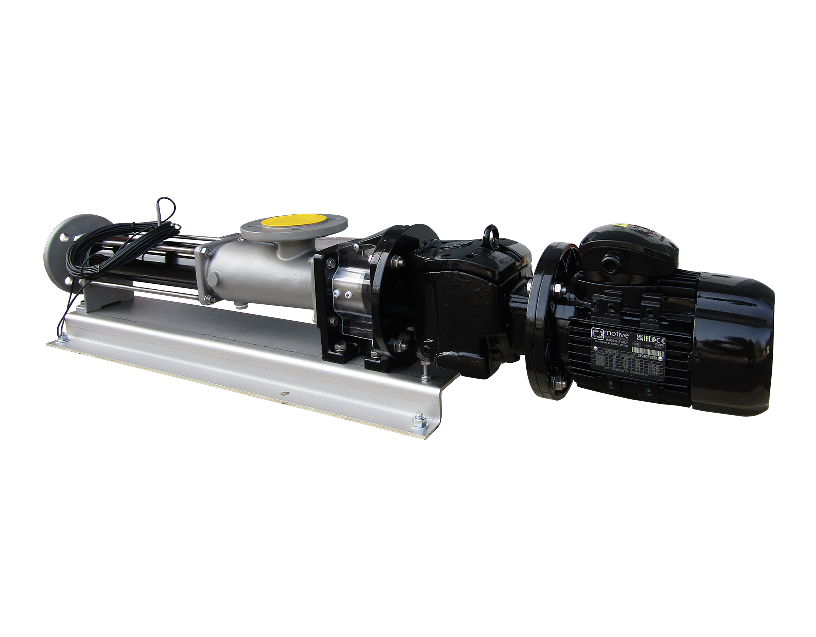
Rotor
Driven by the output shaft of the gearbox, this rotates in a rotary manner within the stator pushing fluid that enters the inlet towards the outlet of the pump. They can be made in a variety of metals and hard chrome plated to suit a variety of liquids and applications.
Stator
The stator is held in place within the pump housing and made from a variety of rubbers such as EPDM, NBR and Viton. They can be assembled in a single piece with a rotor for pressures up to 24 bar. They can also be doubled up, enabling pumps to reach pressures of up to 48 bar. The stator forms much of the body in a progressing cavity pump.
Tie Rods
These are threaded rods which hold the pump outlet flange to the main body.
Coupling Pin
A coupling pin joins the drive shaft to the rotor.
Joint cover
A joint cover can cover the cardan shaft or the pin joint. This protects it from damage, wear and tear or contamination in hygienic pumps.
Lobe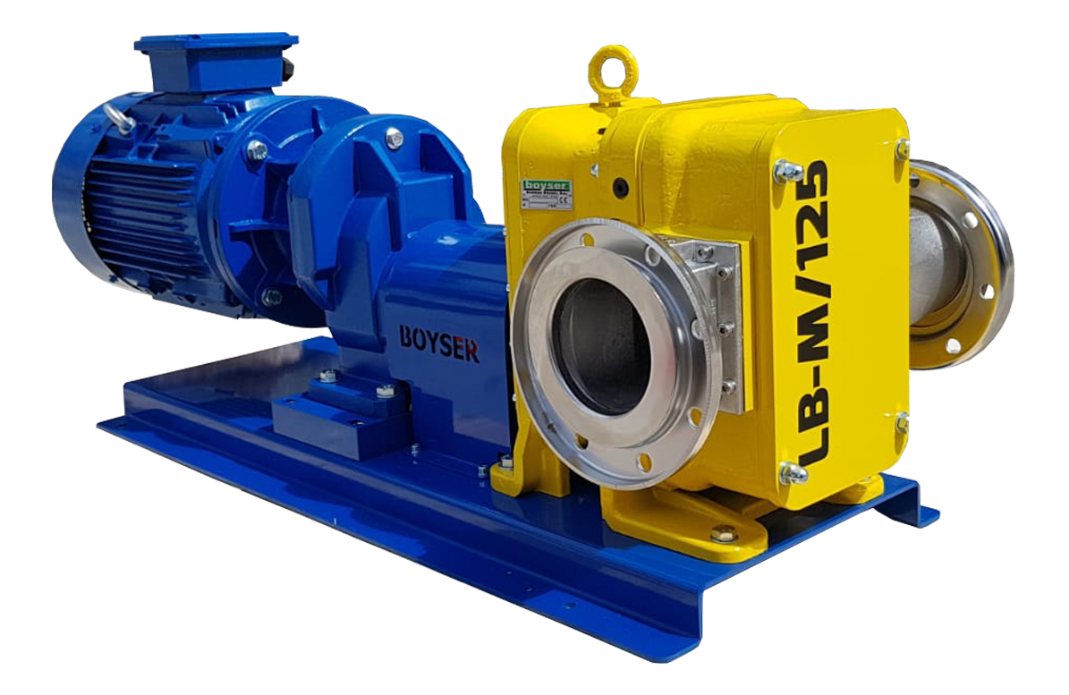
Lobes
A set of lobes which can be manufactured in a variety of rubbers or metals depending on the fluid pumped.
Lobes rotate with the pump head generating the flow and pressure required. Rubber lobed pumps are usually self-priming, whereas metal lobed pumps need a flooded suction.
Gear
Timing gears are located behind the rotating lobes. They ensure the lobes do not touch and rotate at pre-set intervals.
Drive Shaft
Output from the gearbox rotates the drive shaft, this in-turn rotates the driven shaft, rotating one lobe.
Driven Shaft
This is rotated by the drive shaft and controls the rotation via the timing gear of one lobe.
Wear Plates
Wear plates are located on the inside of the pump casing. These sacrificial parts are to protect the casing from wear.
Cover plate
Fitted to the front of the pump casing, these allow for easy access to the internal working mechanisms.
Rotary Piston
Rotor
The piston drives back and forth within the rotor. This happens as the rotor rotates causing liquid to be drawn into the pump and expelled via the outlet.
Piston
Slides back and forth along a rotors groove drawing liquid into the pump inlet.
Double/Triple Screw Pump
Twin Screw
A twin set of screws located side-by-side. These screws rotate within the pump casing causing fluid to be drawn towards the inlet. The fluid increases in pressure and is directed towards the outlet of the pump casing.
The screws are driven separately, with one screw driven via the motor, whilst the other is rotated by external timing gear located at the opposite end of the unit.
It is possible for screws to be mounted in pairs meaning up to 4 screws are in one pump. All screws mesh, ensuring fluid is directed from the inlet towards the outlet.
Driving Screw
A driving screw is the main part responsible for producing flow and pressure within a triple screw pump. It intermeshes with two idler screws to increase fluid pressure with fluid then discharged from the casing. It's driven either by the motor at full speed, or the output shaft of a gearbox at reduced speed for higher viscosity liquids or lower flow rates.
Flow is also controlled by the pitch and depth of chambers along the screw, as well as the diameter of the screws.
Idler Screws
A set of two idler screws intermesh either side of the driving screw. They are driven by the driving screws, helping to produce the flow and pressure required.
Vane Pump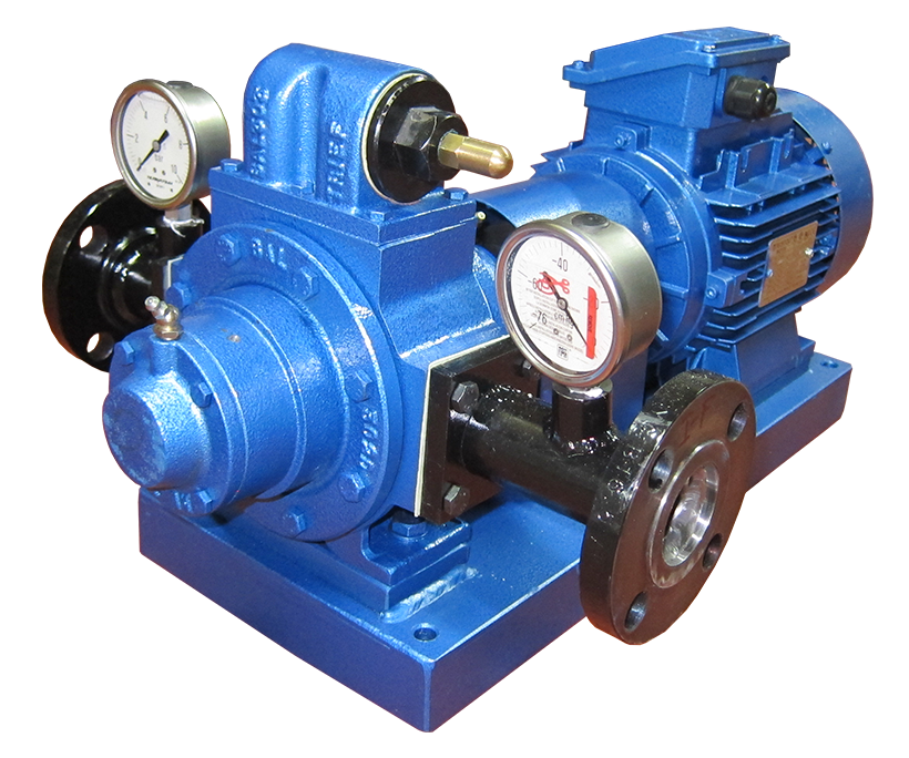
Rotor
The rotor houses the various vanes within the pump. Vanes are slotted within rotor slots, and as it spins, vanes are pushed outwards against the pump casing.
Rods
Rods sit between the rotor and edge of the vanes. They support them within rotor slots and help to push vanes outwards.
Vanes
Vanes sit within rotor slots. They are responsible for producing the flow and pressure within the pump head. Their material is changed depending on the fluid being pumped.
Parts Common to PD Pump Designs
Bearings
Bearings reduce friction between moving parts. They also ensure rotation remains as per the required motion.
CIP/SIP Port
These are ports located on the pump to allow easy cleaning without disassembly of the pump. There is usually an inlet and outlet port that is used to automatically clean pumps. A mixture of chemicals and hot water are used for thorough cleaning between batches or between mixture changes.
Circlip, Snap Ring, Retaining Rings or Seeger
A fastener with open ends containing 2 holes which can be internal or external. They are placed in a machined groove to allow rotation but prevent axial movement. They are also used on a shaft for holding elements in place such as a motor fan blade, a bearing, or a seal.
Gearbox
Depending on the required fluid to be pumped, gearboxes are used to reduce the motor speed, usually operating at 2800rpm or 1400rpm at 50Hz to much lower speeds.
High viscosity fluids or pumps operating 24/7 usually need a low pump operating speed for pump longevity. This is to allow enough time for viscous fluids to flow into the pump head, or to reduce abrasion within the pump by reducing fluid velocity.
Designs can be horizontal meaning the pump head is in line with the motor, or of herringbone design where the motor is at 90° to the pump head.
This enables the motor to be in the shape of an L for compact/space saving installation. A final part of a gearbox is the oil sight level gauge, which shows the amount of oil within a gearbox.
Mechanical Seal
Pump heads are sealed using a mechanical seal or packed gland. A mechanical seal, seals around the shaft and pump casing. This seal consists of two faces and a spring. The faces and spring press against each other forming a seal that's cooled by the pumped fluid. Dangerous or volatile chemicals may require a dual mechanical seal, or cartridge seal design.
O Ring
O rings are used to seal around metal parts, such as within the pump casing, or around drainage ports. Metal itself is unable to create a seal without an elastomer, silicone, or plastic, acting as a barrier. O rings are placed into grooves where they are compressed between mating surfaces sealing the leak path.
Packing
Packed glands are a set of segmented rings. They are wound around the shaft and need the pumped liquid to lubricate the packing and keep it cool. If there is insufficient cooling the packing will burn. It is reliant on liquid leaking from the pump head for its correct function. The packing is tightened against the shaft using the packing press.
Relief Valve
PD pumps continue to build pressure within the pump head and any connected pipework. If the pressure is not relieved in anyway, it will continue to build. If not addressed, it can lead to damage to the pump head and internal parts or failure in connected pipework.
Rubber/Steel Gaskets (Klinger)
Metal reinforced rubber gaskets are used for the sealing of flanged pipework in hazardous conditions. These conditions can be, high pressures and temperature, or handling of hazardous chemicals.
Spring
Used within relief valves and adjusted by rotating clockwise or anti clockwise to adjust relieving pressure.
They are also used in miniature designs of diaphragm pumps to ensure balls return to their original position. Mechanical seals need a spring to supply the pressure required to keep the stationary and rotating seal faces together.
Parts of a Positive Displacement Pump PDF
Download our PDF that gives an in-depth part breakdown of multiple types of positive displacement pumps. Simply click on the PDF image here.
Understanding when a Positive Displacement Pump is best for Your Application
Struggling to understand whether a positive displacement pump is best for your application?
With so many types, designs, differences in applications and liquids - we always recommend speaking to one of our expert engineers via live chat, email or by phone.
Once we have covered your process, application, and desired outcome, we can often suggest a pump type within minutes.


