Go BackGo back
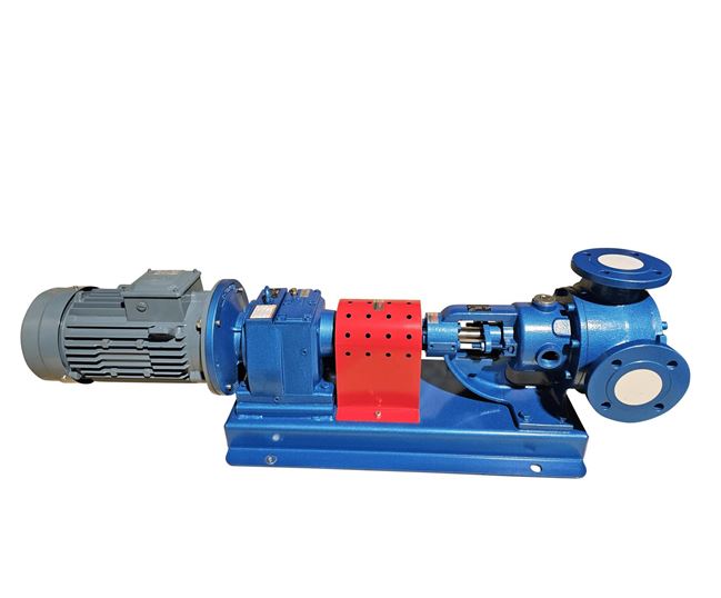
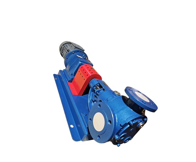
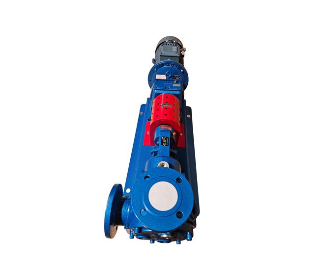
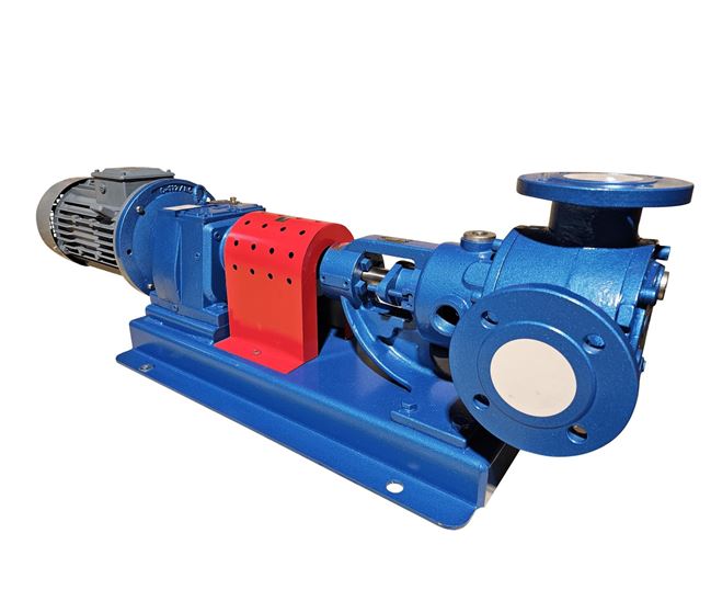
Product code: FIG90 Internal Gear Pump - 90° Flange Connections

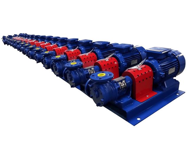
North Ridge FIG90 Internal Gear Pump with 90° Flange Connections

Pump Type - Gear

Max Flow Rate - 200M³H

Max Head - 140M

Pump Materials - AISI304, AISI316, Cast Iron, Cast Steel

Max Temp - 200°C

Max Viscosity - 55,000 cst

Max Solid Passage - 0mm

Self Priming - Y

Inlet/Outlet Sizes - 50mm to 205mm

Drive - AC Electric, Bareshaft

Max Suction Lift - 8M

DOWNLOADS

DESCRIPTION

FIG90 Internal Gear Pump with 90° Flange Connections


Flow Rate

Up to 200 m³/hr

Head (Pressure) Range

1 - 14 bar

Sizes Available

2” - 8”

Operating Temperature Range

0 - 200°C

Viscosity Range

100 – 250,000 SSU

Drive Options

Electric Motor + Gearbox / Belt Pulley   Drive

Power Range

0.75 – 132 kW

Construction Materials

Cast Iron, Cast Steel, AISI 304 – 316 Stainless Steel


Our internal gear pumps are designed to handle clean low – high viscosity lubricating fluids, being positive displacement pump types our FIG90 gear pumps are suitable for high pressure applications up to 14 bar depending on the model configuration selected. The pumping action is done by the rotation of intermeshing gears and a rotor designed to push the fluid at towards the outlet side of the pump, due to the extremely tight clearances between the gears these pumps are only suitable for lubricating clean liquids.


Some of the most common fluids our internal gear pumps are used for are fuels, oils, greases, resins and adhesives. Our gear pumps are manufactured according to CE standards and therefore comply with all current European quality demands and regulations, our simplistic design designed construction with only two moving/rotating components along with the exceptional tight clearance within the internal moving parts is the secret for our gear pumps high efficiency as there is almost zero slip whilst in operation meaning these pump's energy consumption is minimal making them consequently a great option for continuous operation, (24/7) applications.


Our internal gear pumps can be supplied with external bypass valve and external heating jacket upon request, these pumps are also available with ATEX (explosion proof) motors for hazardous non-safe environments and applications, the FIG90 pump range is available with a variety of seal types such as mechanical seal, cartridge seal, packing seal and lip seals.


Thanks to having various construction materials along with a range of pump sizes, different sealing options and their 200 °C max. operating temperature our internal gear pumps can be used for a wide range of applications and almost any non-corrosive clean fluid specifically where a non-pulsating flow is necessary, they can also be supplied with marine class certification upon request hence are perfectly suitable for marine use.


Design Features/Benefits


Available with several sealing options – cartridge seal, packing, single mechanical seal, lip seal etc.

ATEX certified upon request

Supplied with 90° flange connections

High efficiency due to exceptional tight clearances

Fantastic self-priming capabilities

Optional external heating jacket

Manufactured according to CE standards

High Temperature Pump (Up to 200 °C

Available with external bypass valve

Marine class certification upon request


Typical Applications/Fluids:


        Coolant

        Kerosene/gasoline

        Diesel fuel

        Hot oil

        Grease

        Bitumen

        Asphalt

        Edible oils

        Crude oil and fuel oil

        Paint, resins, emulsions and coatings

        Soap and detergents

        Food process plants

        Heat transfer


Learn more about Gear Pumps in our guide

FAQS

No, definitely not! Gear pumps will incur damage even after short periods of dry running. Firstly, the gears require lubrication from the pumped fluid, for example fuel and oil. Dry running without these will cause fast and irreversible damage. The mechanical seal requires lubrication and cooling while the pump is operating. Without the presence of fluid, the mechanical seal will overheat and crack, and this may cause the pump to leak and fluid to enter the motor. There is also the possibility that the motor will burn out. Our advice is to ensure that the pump always has access to fluid while running, the vessel or sump on the inlet side of the pump must never run out of fluid while the pump is active. Level sensors or a float switch can be installed in the fluid chamber ensuring that the pump is turned off in the event there is no fluid. Another way of protecting the pump is to fit a dry running device, this will turn the pump off if it detects that no fluid is entering the pump. If you think that dry running is inevitable, then please speak to us and we will try to select a more suitable pump for your application.
A pump must be primed in order to operate correctly, this means that the pump casing and inlet pipe must be filled with fluid and the air removed before operation. This needs to be done manually by the pump operator for a non-self-priming pump each time the pump is used to avoid damage from dry running. A self-priming pump removes these issues by completing the priming process automatically. The air is removed from the inlet pipework and pump casing when the pump is activated. Self-priming pumps are particularly useful for installations with a suction lift on the inlet side of the pump, the pump will draw the fluid up the pipework by creating a vacuum and removing any air that is present. In ideal conditions, a self-priming pump can lift fluids up to around 8m on the inlet side, however this figure is affected by fluid viscosity, pipework bore and other installation conditions, therefore this figure can be much lower from case to case. Allowances must also be made for wear and tear; suction lift capabilities will be much lower for older and worn pumps.
Please be aware that the figures displayed relate to the largest pump from this range of products, not specific models. For details on viscosity for specific models, please refer to datasheets or contact a member of our sales team.
A clear picture of the pump system is required to make an accurate selection. The main pieces of information required include; a description of the application, bore of pipework, the fluid, viscosity, size and type of solids, flow rate and pressure/head. With these pieces of information, a pump can be sized correctly to ensure it delivers the required flow rate and pressure and that is also operates at its best efficiency point to lower lifetime costs. Knowing if the pump is running intermittently or continuously also allows the correct motor speed to be selected. For instance, a pump running continuously 24/7 will require a slower speed motor rather than a full speed motor. Running the motor slower and oversizing the pump will reduce wear of the motor and the pump, therefore lowering maintenance costs during their lifetime.
An integral bypass is designed to protect the pump and system from overpressure for small periods of time. It is typically set to around 10% higher than the working pressure, it will open and recirculate the fluid inside the pump head when the set pressure is achieved. An integral bypass is only a temporary solution and cannot operate indefinitely, an additional external bypass that runs back to the fluid source is always recommended as a more permanent solution.
ATEX is an abbreviation of “Atmospheres Explosibles”. It is a regulation set out by the European Union to ensure the safety of products that are used to handle flammable products or are installed in environments containing flammable gases, vapours, mists or combustible dusts. For instance, if the pump is being installed in an explosive environment, then only the motor needs to meet the Atex standard stopping it from causing a spark during operation and igniting the atmosphere. However, if the fluid being pumped is flammable, then the pump will also need to meet Atex standards to ensure that no sparks are caused inside the pump itself when the fluid goes through it. It is crucial that an Atex rated pump or motor are used for applications involving explosive environments or flammable fluids, using a non-Atex pump or motor in these situations is extremely dangerous and contravenes health and safety standards.
NPSH is an acronym for Net Positive Suction Head. NPSH measures the absolute pressure present in a fluid.

There are two main ways that NPSH is expressed in a pump system

NPSHa - This is the amount of Net Positive Suction Head available at the pump inlet. NPSHa demonstrates the amount of pressure acting on a fluid as it enters the pump. This measures the amount of pressure between the liquid staying in its current state and forming vapour bubbles (beginning to boil).

NPSHr - This is the amount of Net Positive Suction Head that the pump requires to operate without experiencing the damaging effect of cavitation, thus causing a dramatic reduction in pump performance.

It is very important to pay attention to these values when making a pump selection. Selecting a pump that requires more NPSH than is available in your system will cause fast and long-lasting damage to the pump and thus you will incur large repair costs and downtime.